Fig/Tab
RSS Service
Email Alert
Toggle navigation
Home
About Journal
About the Journal
Editorial Board
The 2nd EB
The 1st EB
Submission Guide
Journal
Just Accepted
Current Issue
Archive
Most Read Articles
Most Download Articles
Most Cited Articles
Subscription
Columns
Publishing Policy
Preprinting Policy
Data Policy
Publishing Ethics
中文
More options
Journal
DOI
ALL
Synthetic Biology Journal
Publication year from
To
All
2020
2021
2022
2023
2024
2025
All
2025
2024
2023
2022
2021
2020
Volume
Issue
Author
Affiliation
Search result
Journal
Loading ...
Publication year
Loading ...
Tab. 2 Common promoters for the
B. subtilis
expression system
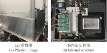
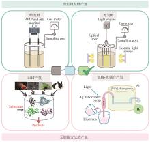
Fig. 9
Prototype built
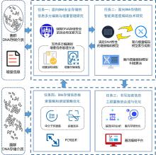
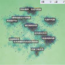
Fig. 1
The architecture of this study
Table 1 Typical genetic circuit-enabled synthetic biosensors and applications
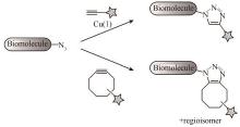
Fig. 3
Bioorthogonal cycloadditions of azides and alkynes to form triazoles
[
13
]
[Terminal alkynes are activated by Cu (Ⅰ) to undergo cycloaddition with azides (top). Cyclooctynes react with azides through a strain-promoted cycloaddition (bottom).]
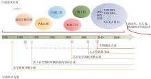
Fig. 5
Development and application of DNA synthesis technology
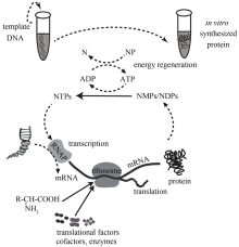
Fig. 2
Cell-free protein expression system
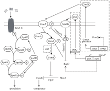
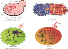
Fig. 3
Processes of competence and spore forming in
B. subtilis
Tab. 3 Typical bio-chemicals and industrial enzymes produced by
B. subtilis
chassis cell
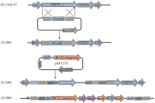
Fig. 2
Design, synthesis and application of synthetic genome
Table 1 Evidence codes used for Gene Ontology annotation
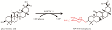
Fig.1
Glycosylation of glycyrrhetinic acid to form GA-3-
O
-monoglucose
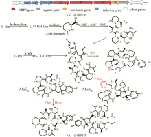
Fig.2
AFNs biosynthetic gene cluster and manipulation of biosynthetic pathway for production on of di-AFNs
Fig.3
Synthetic biology approach for production of erythromycin A
Fig. 1
Stress factors faced in ethanol production by
Saccharomyces cerevisiae
[
13
-
24
]
Fig. 7
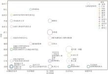
Major PCT patent applicants
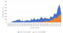
Fig. 2-1
Global patent application trends in the alternative protein industry and patent filing trends in china
Fig. 1
Classification of the routes to produce hydrogen
Fig. 8
PCT patent core technology distribution by country
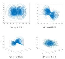
Fig. 2
Chaotic attractor graph of each plane
[
15
]
page
Page 1 of 148
Total 2941 records
First page
Prev page
Next page
Last page