Please wait a minute...
Fig/Tab
RSS Service
Email Alert
Toggle navigation
Home
About Journal
About the Journal
Editorial Board
The 2nd EB
The 1st EB
Submission Guide
Journal
Just Accepted
Current Issue
Archive
Most Read Articles
Most Download Articles
Most Cited Articles
Subscription
Columns
Publishing Policy
Preprinting Policy
Data Policy
Publishing Ethics
中文
IMAGE/TABLE DETAILS
Figure Option
View
Download
Download As Powerpoint Slide
Advances in electro-microbial synergistic systems for value-added conversion of carbon dioxide
HAN Lin, GUO Yuman, LI Yan, CAO Hengheng, LI Jiajing, YANG Minghao, WANG Mengmeng, LI Jinping, LV Yongqin
Synthetic Biology Journal
DOI:
10.12211/2096-8280.2025-070
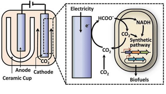
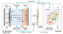
Fig. 10
An integrated electromicrobial process for converting CO
2
into higher alcohols
[
90
]
Extracts from the Article
基于上述优势,研究者已构建出多种高效集成化反应器,用于CO
2
向高附加值化合物的高效转化。Li 等人率先设计并实现了一种典型的原位一体化反应器集成系统,其中将电催化模块与微生物催化模块集成于一个密闭反应器内(图10)[90]。在该系统中,CO
2
首先在电催化阴极上还原为甲酸,作为中间碳源供给后续的生物合成;同时,选用具有固碳与能量积累能力的
R. eutropha
H16作为工程宿主,通过代谢工程破坏其PHB合成路径,并增强其对甲酸的摄取与代谢能力,使其更专一地将甲酸转化为目标燃料。具体而言,经过定向改造的
R. eutropha
H16菌株在以CO
2
和电能为唯一碳源与能源的条件下,实现了异丁醇与3-甲基-1-丁醇等高值生物燃料的合成,终产物浓度超过140 mg/L,验证了该系统在碳中和与绿色能源制备方面的潜力。
Other Images/Table from this Article
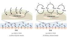
Fig.1
Classifications of electrocatalytic-microbial
in situ
coupling systems
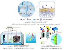
Fig.2
Design of different electrode materials and schematic diagram of the MES systems
Fig.3
Design of artificially regulated MES systems
Fig. 4
MES for C
2+
product synthesis
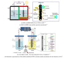
Fig. 5
H
2
-mediated enhancement strategies for MES-1
Fig. 6
H
2
-mediated enhancement strategies for MES-2
Fig. 7
Schematic of enhanced CO
2
-to-CH
4
energy efficiency via redox-mediated cathode functionalization in MES
[
80
]
Fig. 8
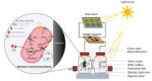
Construction of an artificial photosynthesis system by integrating a photoelectrochemical system with genetically engineered cells expressing rhodopsin and an outer-membrane conduit MtrCAB
[
95
]
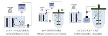
Fig. 9
Three integrated modes of electrocatalytic-microbial
ex situ
coupling systems for CO
2
conversion
[
9
]
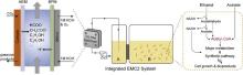
Fig. 11
Schematic illustration of the integrated EMC2 system
[
96
]
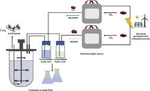
Fig. 12
Schematic of the continuous-flow biohybrid CO
2
electrolysis-fermentation system
[
102
]
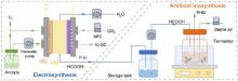
Fig. 13
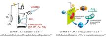
Schematic illustration of the electromicrobial cascade system for artificial glucose synthesis
[
103
]
Fig. 14
Schematic of the spatially separated electrochemical CO
2
reduction reaction (CO
2
RR) and microbial fermentation process for efficient β-farnesene synthesis from CO
2
[
98
]
Fig. 15
Schematic of the sequential CO
2
electrolysis and microbial fermentation system for artificial synthesis of PHB
[
104
]
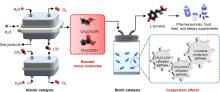
Fig. 16
Schematic illustration of L-tyrosine synthesis from CO
2
using a blended nexus molecular system based on an abiotic/biotic cascade catalysis
[
105
]
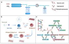
Fig. 17
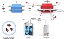
Schematic diagram of the carbon dioxide electrocatalytic platform and microbial conversion for long-chain compound synthesis. a) Schematic illustration of the integrated electrocatalytic/biocatalytic platform system for the synthesis of long-chain compounds from CO
2
. b) Schematic depiction of the fabrication process of the MPN@deCOP@Ag-Cu
2
O electrocatalytic platform. c) Construction of the ethanol utilization pathway
[
106
]
.
Table 1 Representative work:
in situ
vs
ex situ
coupling
Table 2 Comparative analysis of
in situ
and
ex situ
coupling systems